Connection end restraint is ignored for member design. The beam will be subjected to downward loading which will cause a positive moment in the beam.
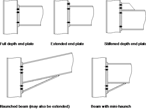
Moment Resisting Connections Steelconstruction Info
Beam Deflection Equations and Formula.

. Load supported bending moment and shear force. Calculation Example Reinforced Concrete Column at Stress. Before discussing the moment capacity calculation let us review the behavior of a reinforced concrete simple beam as the load on the beam increases from zero to the magnitude that would cause failure.
Design a double web cleat connection for an ISMB 400 coped beam to an ISMB 600 main beam so as to. Beam Deflection Equations are easy to apply and allow engineers to make simple and quick calculations for deflection. The effective length of compression flange of the beam is also 8 m.
Moment Capacity of a Beam. Beam to Beam Connection Design Project Worked Example - 7 Made by Date 1-10-00 SRSK Checked by Date Calculation Sheet VK Design Example 7. Dead Moment MD 20 ft-kips Live Moment ML 38 ft-kips Wind Moment Mw 82 ft-kips.
Calculation Example Torsional moment-Stress. The ends of beam are not free to rotate at the bearings. The term analysis method for building frames of a is defined as a general flatplate structural system comprising thin Kirchoff plates.
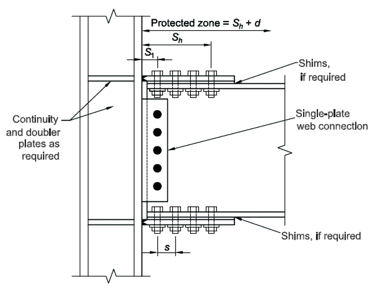
Steel Specification ASTM A992 - Bolts ASTM A325 Loads. Single plate shear connections and ex-tended single plate shear connections. The effective span of beam is 8 meters.
Calculation Example Rod loading Calculation Example Maximum Deflection Calculation Example Member Diagram. FsPsl 08ft Pt Version II 34 - 20 BOLTED CONNECTIONS II Job No. Calculation Example Cantilever Beam with point loads.
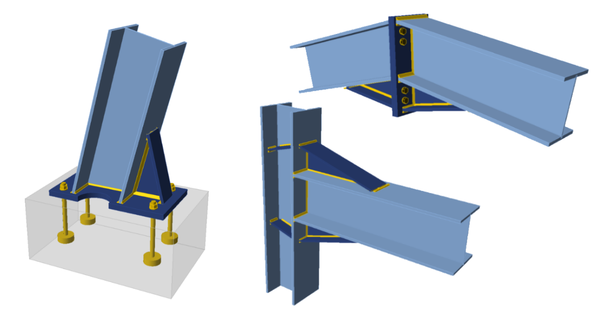
Figure 9 Design Parameters. Example 142 Design a simply supported beam to carry a uniformly distributed load of 44 kNm. Example 1 Design a bolted T-Stub moment connection for the beam shown on Figure 9 supporting both gravity and wind loads.
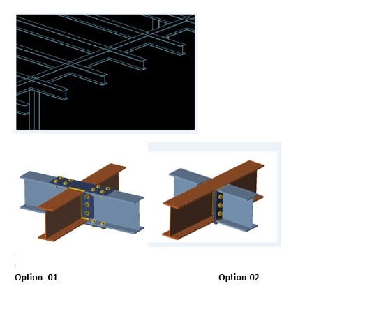
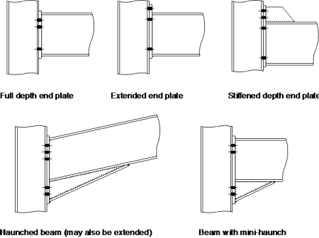
Which are interconnected by onedimensional flexural elements of various shapes and layouts. The first type is used for beam-to-beam and beam-to-column-flange connec-tions where the end of the supported beam frames close to the face of the supporting member. Below is a concise beam deflection table that shows how to calculate the maximum deflection in.
The second type is used for beam-to-beam and. Sheet 1 of 2 Rev Structural Steel Job Title. Analysis Methods for Building Frames.
There are have many different methods of building frame analysis thats are below-. Calculation Example Frame analysis Uniform Load Calculation Example Find the Center of Gravity Surface Calculation Example Design bolted connection of tension plates EC3 Calculation Example Cantilever Beam Calculation Example Cantilever Beam Temperature change Calculation Example Undamped free Vibration Part A. Calculation Example Cantilever Beam with uniform loading.
If youre unsure about what deflection actually is click here for a deflection definition.
Beam To Beam Moment Connection Structural Engineering General Discussion Eng Tips
Moment Connections Calc Them All Idea Statica
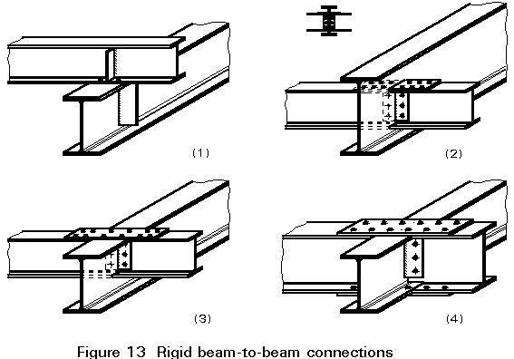
Esdep Lecture Note Wg11

Example Of The A All Bolted Split Tee Connection And B Through Beam Download Scientific Diagram
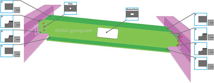
The 7 Most Used Beam Connections Explained Hgg 3d Profiling
Moment Resisting Connections Steelconstruction Info
Moment Connections Calc Them All Idea Statica
Structure Magazine Unanticipated Stresses And The Welded Flange Plate Moment Connection
0 comments
Post a Comment